 One of the most important aspects of torque loading on a gear reducer is the level of counterbalance. Technical Data used in the field explained in petroleum courses in Rawalpindi. Improper counterbalance, either too much or too little, is probably the biggest single factor involved in overloading a pumping unit gear reducer. In general, the counterweights are positioned on the cranks so that their effect approximately balances out the weight of the sucker rod string and a portion of the fluid to be lifted. In some special geometry units such as the Mark II, the counterbalance torque on the gear reducer is out of phase with the torque on the gear reducer exerted by the well load. This means that when the pitman side members go over top and bottom dead center with respect to the reducer slow speed shaft, the reducer torque exerted by the counterweights is either leading or lagging the well load torque. This is accomplished by putting a dogleg in the crank so that the counterweights do not go over top and bottom dead center of the reducer slow speed shaft at the same time as do the pitman side members. The net effect of this combination of torque loading is illustrated. Some more details of petroleum courses in rawalpindi are as under. For any position of the cranks there is a number, when multiplied by the polished rod load, that equals the torque on the gear reducer caused by the well load. This number is called a “torque factor.” As the cranks are rotated through one complete stroke of the pumping unit, the torque factor changes for every crank position. The pattern of torque factors around the pumping cycle is altered by the particular type geometry unit in question. This changing pattern of torque factors, in conjunction with phased counterbalance (see Counterbalance section), is used to an advantage in reducing the net torque on the gear reducer in some cases. Torque factors usually are expressed in inches. TSK Training for Skills and Knowledge is the best institute in Rawalpindi Islamabad for Pakistani Students who wants to join petroleum courses in islamabad.
0 Comments
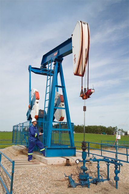 There are many variables that affect the loading on the sucker rod string and pumping unit. Some of these variables are listed. Technical Data used in the field explained in petroleum courses in Rawalpindi. Unfortunately, many of these variables are unknown when design calculations for sizing a pumping unit are made. For a visual representation of some of these loads. A dynamometer card is a continuous plot of polished rod load vs. polished rod displacement, or it may be a continuous plot of polished rod load vs. time. A polished rod load plot can in some instances be useful in analyzing downhole problems as well as identifying the resulting loads on the surface equipment. A typical dynamometer card, When pumping speed is elevated above zero, the card takes on a different shape. Some of the load values are increased over the zero-pumping-speed card shown by the dotted lines and some values are decreased. Some more details of petroleum courses in Rawalpindi are as under. While this section is not intended as a treatise on polished rod dynamometer card interpretation, certain conclusions can be drawn from the card and knowledge of subsurface conditions. As noted under Pumping Unit Loading there are many variables that affect loading on the polished rod. Sometimes some of these variables nullify each other, sometimes they are additive, and sometimes they are shifted time-wise because of rod string dynamics, making it virtually impossible to make a meaningful interpretation of the dynamometer card shape. This is particularly true in deep wells with a relatively elastic sucker rod string. At other times, certain type cards have a very distinctive pattern and downhole problems can be identified quite easily. Dynamometer card that is particularly detrimental to all surface and subsurface equipment. This card depicts a severe fluid pound. The condition generally is caused by attempting to produce fluid at a greater rate than the reservoir will give it up. The result is incomplete pump fillage and a fluid pound when the plunger hits the fluid on the downstroke. If the pound occurs very near the top of the pumping unit stroke, or at a low plunger speed, the effect is not so damaging; however, if the pound occurs at high plunger speeds in the pumping cycle, a progressively detrimental effect and equipment damage is generally the result. If a fluid pound does exist, the operator should make every effort to correct this costly practice by decreasing the displacement of the bottom hole pump. This can be accomplished by either reducing the pumping speed, shortening the stroke length, or installing a smaller-bore bottom hole pump. Sometimes it is necessary to try a combination of these remedies to prevent a decrease in production. TSK Training for Skills and Knowledge is the best institute in Rawalpindi Islamabad for Pakistani Students who wants to join oil field after petroleum courses in Rawalpindi petroleum courses in Islamabad.  The conventional crank balanced pumping unit is the type most commonly used today, especially in the short and medium stroke lengths. Technical Data used in the field explained in petroleum courses in Rawalpindi. It adequately serves a wide variety of field applications. conventional crank balanced unit with the various parts labeled. The rotation of the cranks connected to the pitman side members causes the walking beam to pivot about the center bearing, thereby causing the polished rod to move up and down through its connection to the wire line and horsehead. The adjustable counterweights located on the cranks are heavy metal castings. Fig. 10.2 illustrates the mechanics of the counterbalance system. Adjustment of the counterweights and their effect at the polished rod are discussed later in this section. The air balanced pumping unit is basically the same as the crank balanced unit in that the rotation of the cranks causes the walking beam to pivot and move the polished rod up and down. typical field installation of an air-balanced unit with the various parts labeled. Some more details of petroleum courses in rawalpindi are as under. The unit is compact and relatively light. The long cylindrical tank at the front of the unit houses a piston and air cylinder. Force exerted by compressing air in the cylinder is used to partially counterbalance the well load. A special sealing device is used to prevent air leaks between the piston and cylinder. One of the features of the sealing device is a pool of oil on top of the piston acting as an air seal. Fig. 10.4 shows how the counterbalance force works to partially offset the well load. An auxiliary air compressor is used to maintain the system air pressure at an optimal working level. The operation of the compressor normally is controlled automatically by a pressure switch to maintain air pressure within a manually preset range. TSK Training for Skills and Knowledge is the best institute in Rawalpindi Islamabad for Pakistani Students who wants to join petroleum courses in Islamabad. 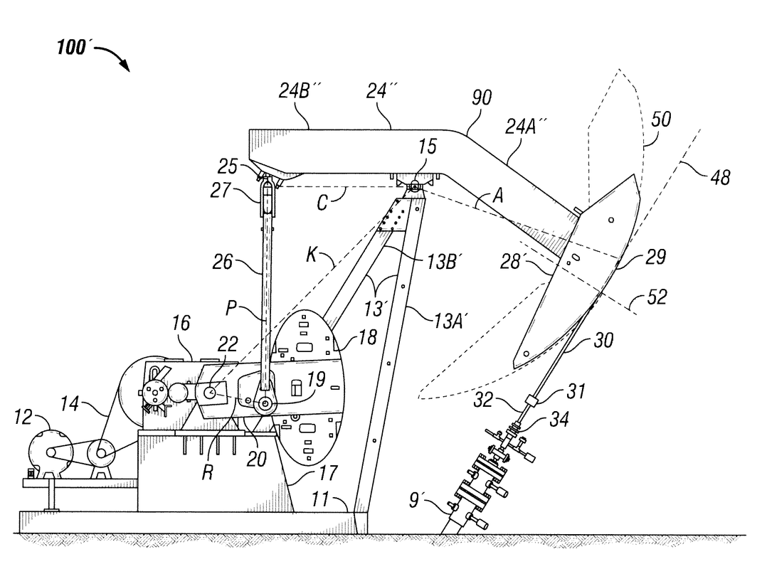 Pumping units are manufactured in various geometric configurations in addition to methods of counterbalance. Technical Data used in the field explained in petroleum courses in Rawalpindi. As mentioned before, beam balanced and conventional crank balanced units are Class I lever systems, and air balanced and Mark II units are Class III lever systems. Within these two lever systems are variations effected by moving the gear reducer on the structural base with respect to the equalizer or cross yoke. In the case of the Mark II, the cross yoke is not located directly above the slow speed shaft of the gear reducer but shifted forward toward the horsehead. This shifting, accompanied by a specified direction of rotation of the cranks, results in a longer time interval for the upstroke and a shorter time interval for the down stroke. Some more details of petroleum courses in Rawalpindi are as under. The type of pumping unit best suited for a particular pumping problem very often is a matter of personal prcference. The conventional crank balanced pumping unit is the choice of many operators mainly because it has been readily accepted by field personnel for many years. Many other operators’ choice is the Mark II special geometry unit with its capability of a more uniform torque pattern on the gear reducer. Usually these special geometry units will require one size smaller gear box size than other type units for a particular application. The American Petroleum Inst. (API) lists standard gear box sizes in their specification API Spec 1lE. ’ Other operators specify the air balanced pumping unit, which is readily adaptable to platform or pier installations and other unstable substructures. This is because the inertia and shaking forces of air balanced units are very low. Air-balance units also are compact and light in weight compared with other types of pumping units of the same structural and gear box rating. The beam balanced pumping unit is manufactured only in the smaller sizes and economics is the prime factor for selecting this unit type. TSK Training for Skills and Knowledge is the best institute in Rawalpindi Islamabad for Pakistani Students who wants to join oil field after petroleum courses in Islamabad. |
AuthorWrite something about yourself. No need to be fancy, just an overview. Archives
December 2016
Categories |
 RSS Feed
